External links now open in a new browser tab - turn this off in your UCP - Read more here.
Sbeckman7's Project: BR1
There is a reason they call it "building from the bottom up". You need to design the main frame rails and cross members first. Your next sketch should be a plan view that has measurements from your existing sub frames. How far apart are the control arm mounting points? How far apart are the rear sub-frame mounts? Get to the point in your design where you have a quantity of material needed to turn a pile of parts on the floor into a rolling chassis. Don't worry about looks, safety, seats, etc right now. You have to plan/build the project in logical stages. You can't build a roll bar without a frame to weld it to.
Last edited by tsmall07 on Sep 10, 2010 12:59 PM, edited 1 time in total.
-
Tammer in Philly
- Posts: 10719
- Joined: Feb 12, 2006 12:00 PM
- Location: CHI, IL
^^^^^^^^^^^^^^^^^^^^^^^
This man speaks the truth, with one exception: your steering gear will put the wheel at a specific place, which dictates where your seat will go. I'd include that as one of the "hard points" to design around.
You are at a huge advantage because you have known suspension hard points, and that dictates most of your dimensions. Think about how a Corvette is built, as it's still pretty-much body-on-frame (body heavily bonded to frame and not easily removable, but you get the idea). What dimensions do you need to know to build this?

Those are the dimensions you need to plan around. Width is dictated by your suspension locating arms in the front and half shafts in the rear, plus or minus a couple inches due to wheel offset as a variable. Length is more flexible; you've already thought about shortened driveshafts and you can play with custom engine mounts to move the motor back if you want a lower front end. Ride height is largely dictated by the use of the stock suspension arms; when you put the subframe too low, you run into bump-steer issues as the camber and toe curves go wacky very quickly with compression. Custom arms could get around that issue, but that's a lot of design/fabrication/expense. Better, perhaps, to just plan on having a relatively high-riding car.
I still think it'd be pretty easy to make the suspension work with an A-arm front instead of the strut, and that'd be ridiculously compact, but it may be even easier to retain a strut setup but ditch the stock housing and instead, go with a shorter coilover and incorporate an upper mount into the tube frame. E30 camber plates work on an E28, so you can design around the stock upper mount and retain a lot of variability in the final product.
Some of the things you'll want to think about are discussed at length here: http://www.kimini.com/index.html. This build is very different from yours, but it's a ground-up build that fits around a stock motor and other off-the shelf parts.
-tammer
This man speaks the truth, with one exception: your steering gear will put the wheel at a specific place, which dictates where your seat will go. I'd include that as one of the "hard points" to design around.
You are at a huge advantage because you have known suspension hard points, and that dictates most of your dimensions. Think about how a Corvette is built, as it's still pretty-much body-on-frame (body heavily bonded to frame and not easily removable, but you get the idea). What dimensions do you need to know to build this?

Those are the dimensions you need to plan around. Width is dictated by your suspension locating arms in the front and half shafts in the rear, plus or minus a couple inches due to wheel offset as a variable. Length is more flexible; you've already thought about shortened driveshafts and you can play with custom engine mounts to move the motor back if you want a lower front end. Ride height is largely dictated by the use of the stock suspension arms; when you put the subframe too low, you run into bump-steer issues as the camber and toe curves go wacky very quickly with compression. Custom arms could get around that issue, but that's a lot of design/fabrication/expense. Better, perhaps, to just plan on having a relatively high-riding car.
I still think it'd be pretty easy to make the suspension work with an A-arm front instead of the strut, and that'd be ridiculously compact, but it may be even easier to retain a strut setup but ditch the stock housing and instead, go with a shorter coilover and incorporate an upper mount into the tube frame. E30 camber plates work on an E28, so you can design around the stock upper mount and retain a lot of variability in the final product.
Some of the things you'll want to think about are discussed at length here: http://www.kimini.com/index.html. This build is very different from yours, but it's a ground-up build that fits around a stock motor and other off-the shelf parts.
-tammer
That's true to a point. Steering shafts can be shortened/extended fairly easily. There is a company that sells bolt on steering shaft extensions that go directly behind the wheel. I can't think if it right now, though.Tammer in Philly wrote: with one exception: your steering gear will put the wheel at a specific place, which dictates where your seat will go. I'd include that as one of the "hard points" to design around.
Also, with a tube chassis, you can wait until your have your steering wheel mounted and weld the seat support bars wherever you want. You should have your steering set before you place the seat.
Good Start.sbeckman7 wrote:Main frame members are dimensioned. Now time to order some metal
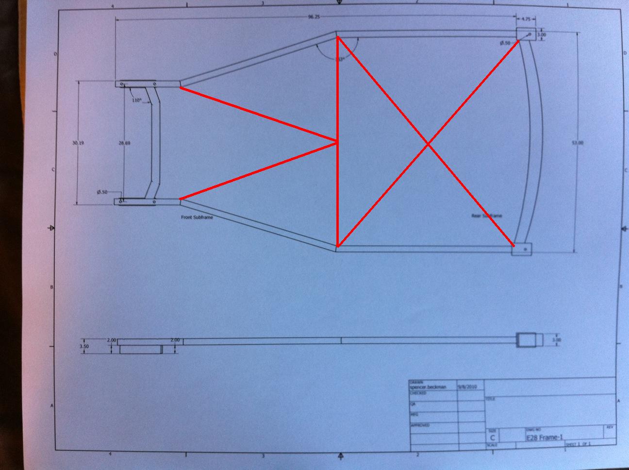
After looking at that, I think you should go with some 2x4 tube steel for the main frame. That will make it a lot easier to make everything square. You'll be able to miter/weld the frame together instead of trying to make such complex bends with round tube. You would probably be ok with 4x2x11 GA (.120 wall). I'd get someone else's opinion, though. This will also allow your frame to have more depth. You'll need bracing in the frame to keep that thing from twisting up. Here is my quickie bracing design:

The idea behind what I did there is that it will provide tortional rigidity while still (hopfully) leaving room for the trans. You have to keep in mind that your drivetrain will not sit on top of the frame. It will have to go through/under parts of the frame. The 2x4 tube will give you more flexibility in this way. The bracing I drew (and everything else after) should be round tube. Also, don't build what I drew in 5 minutes without much extra thought without verifying what will be in the way. You may have to bend some of the bracing up out of the page if you get what I'm saying.
Join pirate4x4.com and look for a guy that goes by "Carwash". I used to get my metal through him and his prices were stupid low. It's been a few years, though.
Just for the record, this seems like exactly what I want to do. To begin planning, I just set up the subframes again at the correct wheelbase. The bottom of the front subframe is currently sitting 5.25" above the ground and the bottom of the rear subframe (measured at the mounts) is just about 10" off the ground. My question is what is the clearance on them when the cars are on the road? Since I have no load, I don't know where the subframes should be loacation with respect to the arms. If anyone could give me an estimate from the ground to the subframes as well as the ground to the tops of the struts, that would be greatly appreciated... That is the best way to do it, right? Measure how they are on the car and then do some height-change calculations due to weight?Ride height is largely dictated by the use of the stock suspension arms; when you put the subframe too low, you run into bump-steer issues as the camber and toe curves go wacky very quickly with compression. Custom arms could get around that issue, but that's a lot of design/fabrication/expense. Better, perhaps, to just plan on having a relatively high-riding car.
...it may be even easier to retain a strut setup but ditch the stock housing and instead, go with a shorter coilover and incorporate an upper mount into the tube frame. E30 camber plates work on an E28, so you can design around the stock upper mount and retain a lot of variability in the final product.
Got fairly accurate measurements of the engine dimensions (out of car) and subframe clearances in the car (measured from another 535i with a five speed):
Ground to bottom of rear subframe: 9"
Ground to bottom of front subframe: 5 5/8"
Ground to control arm label: 9 1/16"
Ground to top of strut: about 31"
Engine: 20" wide, 30" long, 28" tall from oil pan, 25" from block
Bell housing: 7" radius


New dimensions for main pipes

Final Design sketch
Ground to bottom of rear subframe: 9"
Ground to bottom of front subframe: 5 5/8"
Ground to control arm label: 9 1/16"
Ground to top of strut: about 31"
Engine: 20" wide, 30" long, 28" tall from oil pan, 25" from block
Bell housing: 7" radius


New dimensions for main pipes

Final Design sketch
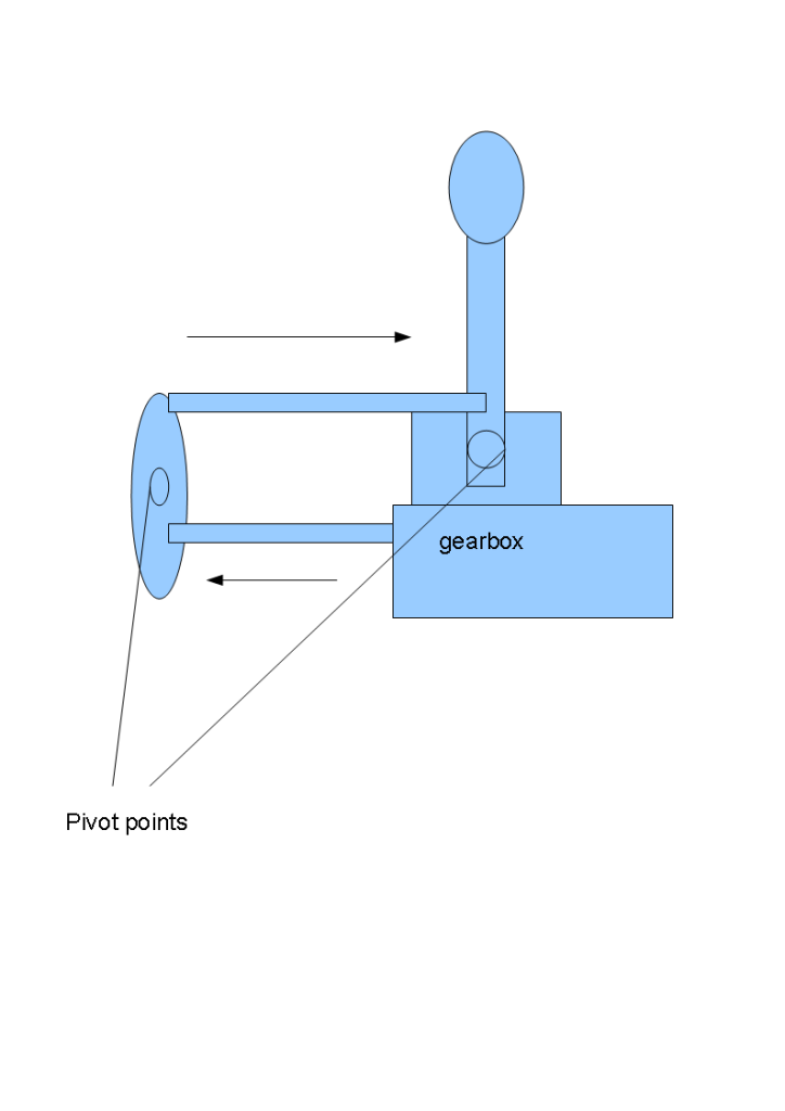
Today I went home to grab the transmission and bell housing so I could finish off my interior dimensions. After attempting and failing to clean it properly, I put it up to the rough ride height on some wood blocks to see how much space I was working with. It's going to be cozy  That said, the footwells are not any skinnier than in a real Caterham. As for the issue of the drive train length, the engine and transmission will fit comfortably tucked just behind the front axle. The pictures of the car as it sits accurately show the placement of the transmission. I tried to show how the existing setup will not be ideal for the location of the shifter, so after a few minutes of thinking I came up with the two proposed linkages that should work very well. I will be shortening the height of the stock shifter (while knowingly increasing shifting effort). The only trick will be figuring out how to set a ball joint in a steel plate. I would assume that some hardware supply stores sell something to suit my needs, but that will be worried about later. Currently working on finding a suitable metal seller.


-
mooseheadm5
- Beamter

- Posts: 23035
- Joined: Apr 08, 2009 10:30 PM
- Location: Charlottesville, VA
- Contact:
So your car will have a 2D frame with a body sitting on top? You are going to be lacking a lot of torsional rigidity that could/should be provided by a tall tunnel. You will want to tie that into the upper shock/strut mounts. Front and rear firewalls should also be braced.
I think your shifter will give you the wrong shift pattern (reversed front to rear) and may not give the correct rotational movement to go from left to right through the pattern. Try to keep the number of joints minimal. Linkage kinematics is a difficult thing with something that needs movement like that.
I think your shifter will give you the wrong shift pattern (reversed front to rear) and may not give the correct rotational movement to go from left to right through the pattern. Try to keep the number of joints minimal. Linkage kinematics is a difficult thing with something that needs movement like that.
...I think you're right about the shift linkage. It works front/rear but I'm not so sure about rotational movement. Any ideas on how to move the shifter to above the gear box? People said it could be done earlier but I am having a hard time with the design.
The frame will be much more structurally sound than in the picture, once again the only reason I drew it is to get dimensions for the design of the body.
The frame will be much more structurally sound than in the picture, once again the only reason I drew it is to get dimensions for the design of the body.
-
mooseheadm5
- Beamter

- Posts: 23035
- Joined: Apr 08, 2009 10:30 PM
- Location: Charlottesville, VA
- Contact:
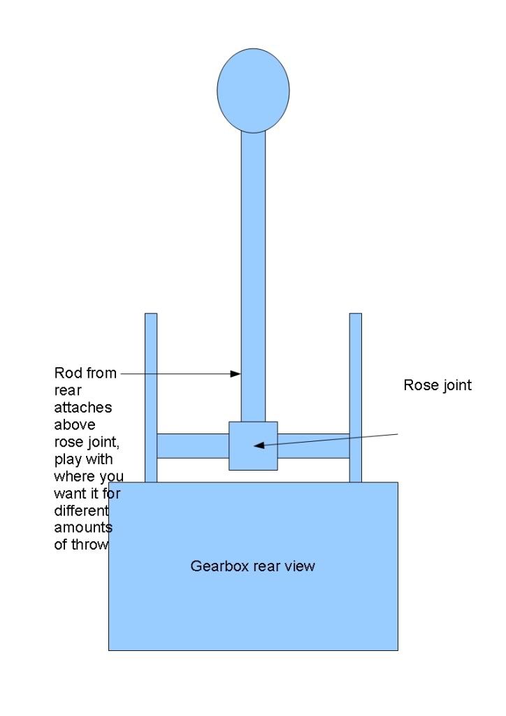
looking at your gearlever diagram,from the rear you have the pivot with 2 rods attached,one below the pivot for the original and one above the pivot for the extension to the new gear lever position.why have you attached this to a point below the pivot on the gear lever?if you attached it ABOVE the pivot point on the gearlever it would then be doing the same as a standard (stock) item.thats how i have seen it done on countless rear engine setups after converting front engine to rear engine (vw golfs etc.)
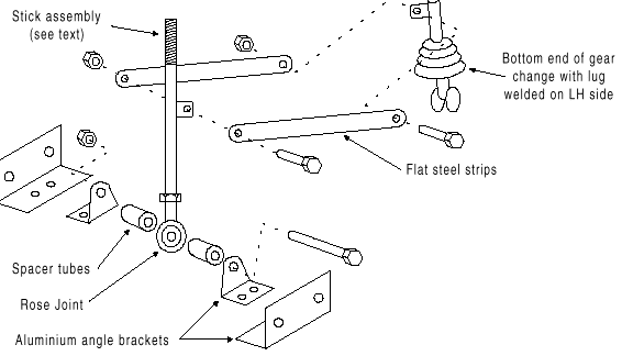
a bit like this crude drawing

a bit like this crude drawing

-
mooseheadm5
- Beamter

- Posts: 23035
- Joined: Apr 08, 2009 10:30 PM
- Location: Charlottesville, VA
- Contact:
I figured this out yesterday, but hadn't had time to post about it (though I wasn't going to post a complete diagram on how to do it since this is his project.)
This will work, and you can use some of the factory stuff at the trans if you modify it properly. In addition, you can make the throw adjustable if you make the linkage connection height adjustable.
This will work, and you can use some of the factory stuff at the trans if you modify it properly. In addition, you can make the throw adjustable if you make the linkage connection height adjustable.
You'll probably have better luck searching for a heim joint in the USA rather than a rose joint. Different names for the same thing.gsracing wrote:the rose joint allows side to side movement
Last edited by tsmall07 on Sep 29, 2010 11:28 AM, edited 1 time in total.
ah,there we go,another word we use differently,who says americans speak english?lol
anyway,imagine this on a larger scale for the front half of the gear lever set up,it shows a similar setup perfectly.the rose or heim joint allows the sideways movement while it can move frward and back as the joint can slide about the bar.
http://www.youtube.com/watch?v=ImCt-C9U3cg
anyway,imagine this on a larger scale for the front half of the gear lever set up,it shows a similar setup perfectly.the rose or heim joint allows the sideways movement while it can move frward and back as the joint can slide about the bar.
http://www.youtube.com/watch?v=ImCt-C9U3cg
gsracing wrote:ah,there we go,another word we use differently,who says americans speak english?lol
wikipedia wrote:The spherical rod end bearing was developed by the Germans in World War II.[1] When one of the first German planes to be shot down by the British in early 1940 was examined, they found this joint in use in the aircraft's control systems. The H.G. Heim Company was given an exclusive patent to manufacture these joints in North America, while in the UK the patent passed to Rose Bearings Ltd.[2] The ubiquity of these manufacturers in their respective markets led to the terms heim joint and rose joint becoming synonymous with their product. After the patents ran out, the common names stuck although "rose joint" remains a registered trademark of Rose Bearings Ltd.
Who says people from Great Britain speak English?
lol,might be in the name,ENGLAND, with the people being ENGLISH,but to be honest,youre right, most youths nowadays cant fathom the queens english! (im only 30 but christ,things have changed!):lol:tsmall07 wrote:gsracing wrote:ah,there we go,another word we use differently,who says americans speak english?lolwikipedia wrote:The spherical rod end bearing was developed by the Germans in World War II.[1] When one of the first German planes to be shot down by the British in early 1940 was examined, they found this joint in use in the aircraft's control systems. The H.G. Heim Company was given an exclusive patent to manufacture these joints in North America, while in the UK the patent passed to Rose Bearings Ltd.[2] The ubiquity of these manufacturers in their respective markets led to the terms heim joint and rose joint becoming synonymous with their product. After the patents ran out, the common names stuck although "rose joint" remains a registered trademark of Rose Bearings Ltd.
Who says people from Great Britain speak English?
good bit of info that though,never knew that,seems we ripped off the germans then.


