Sbeckman7's Project: BR1

General conversations about BMW E28s and the people who own them.
sbeckman7
Posts: 560
Joined: May 27, 2010 12:43 AM
Location: Marin, California

Post by sbeckman7 »

Al, you were right about the wheels! I had incorrect dimensions for the tire diameters, originally drawing them as 2" too small. Here are the updated pictures along with the new roll bar design, which was included in the drawing only for aesthetic purposes. In other words, I will not slap it on the real car like it is on the drawing.

Image
Image
Image

When I am able to do so, all rims will be widened by 1.5" thanks to new lips for the RS's. The widths will be 8.5" for the front and 9.5" for the rear, with 245 and 265 width tires respectively.
sbeckman7
Posts: 560
Joined: May 27, 2010 12:43 AM
Location: Marin, California

Post by sbeckman7 »

Got the frame welded today but unfortunately the pipes bent from the heat of the welding so they're 1 1/16" off. Gotta cut and re-weld them at school..
mooseheadm5
Beamter
Beamter
Posts: 23035
Joined: Apr 08, 2009 10:30 PM
Location: Charlottesville, VA
Contact:

Post by mooseheadm5 »

Who did the welding? They might have gotten too much heat into it, which is easy to do with TIG.
tsmall07
Beamter
Beamter
Posts: 12775
Joined: May 22, 2006 4:32 PM
Location: Springfield, vA

Post by tsmall07 »

Sounds like you need a better welder. I hope you didn't pay him for that.
sbeckman7
Posts: 560
Joined: May 27, 2010 12:43 AM
Location: Marin, California

Post by sbeckman7 »

Nope my friend did it to help me out. But in reality I think one extra trip to the shop is worth the 100+ bucks im saving.

Image
Image
mooseheadm5
Beamter
Beamter
Posts: 23035
Joined: Apr 08, 2009 10:30 PM
Location: Charlottesville, VA
Contact:

Post by mooseheadm5 »

So is it fixed?
If not, try welding it with the subframes attached, and maybe clamp it to some temporary supports while he is welding it. Tell him not to weld in long lines but to tack it all around or it'll put too much heat into the joint and warp things.
sbeckman7
Posts: 560
Joined: May 27, 2010 12:43 AM
Location: Marin, California

Post by sbeckman7 »

mooseheadm5 wrote:So is it fixed?
If not, try welding it with the subframes attached, and maybe clamp it to some temporary supports while he is welding it. Tell him not to weld in long lines but to tack it all around or it'll put too much heat into the joint and warp things.
Sounds like a plan. It's not fixed in those pictures. I'm going to bring it to school, cut it and re-align it there while its on the subframes, and then heavily tack weld it with the mig. I'll tell him to go a little slower this time ;)
mooseheadm5
Beamter
Beamter
Posts: 23035
Joined: Apr 08, 2009 10:30 PM
Location: Charlottesville, VA
Contact:

Post by mooseheadm5 »

Go ahead and tack some cross bracing made from scrap. That will encourage the frame to stay in shape during welding.
It isn't going fast that is the problem. It is too much concentrated heat. He should do a little weld on one joint, then move to another. TIG can put a lot of heat into a part in a short time and if he keeps concentrating on one line of weld he is sure to warp it.
sbeckman7
Posts: 560
Joined: May 27, 2010 12:43 AM
Location: Marin, California

Post by sbeckman7 »

Oh got it. Alright I'll tack some supports in as well
Tammer in Philly
Posts: 10719
Joined: Feb 12, 2006 12:00 PM
Location: CHI, IL

Post by Tammer in Philly »

sbeckman7 wrote:Oh got it. Alright I'll tack some supports in as well
+1 to what Moosehead said. I know one trick used by my cage builder was to brace opposing tubes with lengths of lumber to prevent twist and warping while welding. Tacking in crossbeams would have the same effect. Glad to see the progress, though!

-tammer
sbeckman7
Posts: 560
Joined: May 27, 2010 12:43 AM
Location: Marin, California

Post by sbeckman7 »

Tammer in Philly wrote:
sbeckman7 wrote:Oh got it. Alright I'll tack some supports in as well
+1 to what Moosehead said. I know one trick used by my cage builder was to brace opposing tubes with lengths of lumber to prevent twist and warping while welding. Tacking in crossbeams would have the same effect. Glad to see the progress, though!

-tammer
Me too! So, next will either be the roll bar or the floorpan. not sure what I should do next..
sbeckman7
Posts: 560
Joined: May 27, 2010 12:43 AM
Location: Marin, California

Post by sbeckman7 »

Today I just brought the frame back to the high school and did a mock-up to see how much the new frame design changed things. Apart from the dramatic difference in the height of the side rails, I had a bit more foot room at the end of the footwell, although it's still a pretty cozy fit. So, I'm glad I redid it. When I start on the floor, it's going to be flush with the bottom of the rails and following the previous design, although the lower height will give me room for more reinforcement in the transmission tunnel area. As always, here are a few pictures:
The tape measurers represent the engine at it's tallest point (being mounted vertically with no slant). The future coilovers will land the tops of the strut towers a few inches below the engine, allowing me to create a nice curved profile for the sides of the car. I plan on bulging the sides out on the body work to allow for arm room (maybe even an armrest) and little cubbies for storing things like small groceries, cameras, whatever I need to store.

Image
Image
Image
Image
Image
Image
tsmall07
Beamter
Beamter
Posts: 12775
Joined: May 22, 2006 4:32 PM
Location: Springfield, vA

Post by tsmall07 »

I dig it. That's got the potential to be one sweet ride! :up:

I can't wait to get a ride in it. :cool:
sbeckman7
Posts: 560
Joined: May 27, 2010 12:43 AM
Location: Marin, California

Post by sbeckman7 »

tsmall07 wrote:I dig it. That's got the potential to be one sweet ride! :up:

I can't wait to get a ride in it. :cool:

Yeah! First thing I'm going to do when it's done and registered is give a ride to everyone who helped me out on it. Are you local at all? Doesn't look like CA plates on your car
tsmall07
Beamter
Beamter
Posts: 12775
Joined: May 22, 2006 4:32 PM
Location: Springfield, vA

Post by tsmall07 »

No, I'm in Virginia. I spent a summer in Oakland/SF 2 years ago. I'm sure I'll be back that way again.
sbeckman7
Posts: 560
Joined: May 27, 2010 12:43 AM
Location: Marin, California

Post by sbeckman7 »

Some good stuff happened today. The car is finally sitting on its own! I corrected the bend in the frame by cutting and re-welding the right side right after the 7" drop. I also reinforced it with two 1"x1"x1/8" square tubing. It was originally just to hold the frame steady while I fixed the frame, but I put them in the locations of the two cross-beams following my previous floorpan drawing. Keeping in mind that some of this structure will be used to support the drivetrain, would you guys say that 1.5" or 2" pipe would be ideal? Wall thickness would probably be .120". Anyway, here are the pictures from today, completed by a cleaned up workspace :)

Image
Image
Image
Image
Image
e281985
Posts: 1089
Joined: Mar 23, 2008 10:59 AM
Location: Cleveland, OH

Post by e281985 »

I have to say I'm extremely jealous. Building a car like this has always been a dream of mine, I have been following this thread since it began and your progress is awesome!
I can't wait to see this thing finished.
sbeckman7
Posts: 560
Joined: May 27, 2010 12:43 AM
Location: Marin, California

Post by sbeckman7 »

e281985 wrote:I have to say I'm extremely jealous. Building a car like this has always been a dream of mine, I have been following this thread since it began and your progress is awesome!
I can't wait to see this thing finished.
Thanks man! I cant wait either :cool:
sbeckman7
Posts: 560
Joined: May 27, 2010 12:43 AM
Location: Marin, California

Post by sbeckman7 »

Playing around with the body design on Inventor. I can picture the car just fine in my head but the computer program isn't really cooperating. Here's what I was able to make, and I'll paint the rest of the picture with words.

Front View:
Image
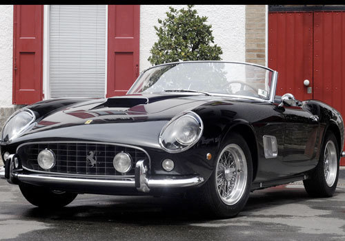
What wasnt captured in Inventor: I want all of the sides of the car to be well rounded off, starting at the nose and flowing over the flared rear wheel arches. So the "grill" will be more of an oval to keep the vintage styling in check. The hood itself will be contoured, with peaks at the outside (by the fenders) and a small bulge in the middle, where a subtle scoop will reside. So there will be two shallow dips in the body work of the hood, between the bulges. Couldn't find any examples of the exact shape but think of a more curvy version of both ferari california hoods.
Image
Image

The fender extensions themselves will be tapered from top to bottom, like the gorgeous Alpine A110: Image


The rear view:
Image

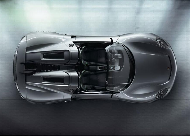
I didn't want the double-bubble feature to continue down the entire body but I haven't figured out how to accurately shape them. Ideally they would stop when the bottom of the bubble is level with the top of the rear arch. This would allow for the rear end of the car to blend together in a much cleaner way. Theyy will also be completely rounded, not cut off like in the picture. Sort of like if the same bubble features on the porsche 918 concept fully blended into the bodywork shortly after those black rectangles.
Image
On the note of the 918, I have been toying with the idea of a similary styled rear spoiler to put a little more downforce on the rear wheels. Like the tiny blue lip (not the massive black spoiler) integrated into the rear of the car, only mounted higher up and with a larger surface area:
Image

The silhouette is the most accurate part of the virtual model, but you can see where the continuation of the double-bubbles interferes with the side lines of the body in the CAD drawing:

Image


Top silhouette is somewhat accurate as well; the fenders and nose need to be rounded off.
Image


Again showing how the rear of the bubble interferes with the side lines. I think I'll bring the rear end of the messed up line up more, giving it more of a horizontal angle.
Image
Last edited by sbeckman7 on Feb 13, 2011 12:27 PM, edited 1 time in total.
sQuirly
Posts: 651
Joined: Apr 16, 2007 10:35 PM
Location: SE CT

Post by sQuirly »

you'll find that to create the body design you want, in inventor or solidworks, you will have to leave boss-extrude & fillet to the wayside and start working with 3d sketch and surfacing. last time i was able to actually play around I started with my 2D ortho views and projected the lines for different features to different planes relative to were i was looking for them to be and moving around a bunch 3d splines till i got what I was looking for.


an important thing to remember is if it is that hard to model it think about how hard it will be to fabricate.

great start and I like were you are going with your styling.
sbeckman7
Posts: 560
Joined: May 27, 2010 12:43 AM
Location: Marin, California

Post by sbeckman7 »

Small update today: got the front springs off of the struts to get ready for the coilover kit. They should arrive next week, and since we have no school then im hoping to meet my teacher there for one day while he does cleaning.
Last edited by sbeckman7 on Feb 22, 2011 2:45 AM, edited 1 time in total.
sbeckman7
Posts: 560
Joined: May 27, 2010 12:43 AM
Location: Marin, California

Post by sbeckman7 »

Since I couldn't update the log during our trip to Chicago, here's what got accomplished last wednesday:

This will hopefully be the new spring location, bringing the overall height of the strut down a good 4 inches or so.
Image

As reccommended by the folks at Ireland Engineering, 350 lb/in springs in the front and the eibach springs (they said 240 lb/in) in the rear:
Image
Tammer in Philly
Posts: 10719
Joined: Feb 12, 2006 12:00 PM
Location: CHI, IL

Post by Tammer in Philly »

When you go to a coilover and a shortened strut, you are likely to get interference between the tire and the spring. Your two options are to move the spring up (shorten the spring and raise the perch to maintain the same overall height), or to move the wheel out. As you are designing your own fenders, you have room for all the spacer you want. I'd install 80mm studs in the hub so you have a lot of flexibility to play with spacer thickness, and don't have to buy a bunch of different lug bolts. Pushing the front wheels out 20mm will allow you plenty of room to run a 60mm or 2.25" diameter spring and still have room to adjust camber. It should also allow you to run a taller spring and maintain more overall suspension travel.

Looking great.
-tammer
Last edited by Tammer in Philly on Feb 22, 2011 12:34 PM, edited 1 time in total.
sbeckman7
Posts: 560
Joined: May 27, 2010 12:43 AM
Location: Marin, California

Post by sbeckman7 »

Tammer, I had been discussing that exact issue with Jeremey over at Ireland Engineering and he told me a good way to measure the spring location to make sure that doesn't happen. However, for some reason I never thought to run spacers; that's a great idea. And it can't hurt the stance of the car either.
sbeckman7
Posts: 560
Joined: May 27, 2010 12:43 AM
Location: Marin, California

Post by sbeckman7 »

Update: with this project locked away at school and my car at the body shop, I'm suffering withdrawal. Quite Badly...
gidgaf
Posts: 391
Joined: Feb 22, 2011 10:23 PM
Location: LAX, Kalifornia

Post by gidgaf »

I live in Los Angeles. A car in that condition is called "good/ fair" in CList terms around here. For that money you got a good deal. Please keep posting works in progress pics, as well as mechanical anecdotes as you go along.
BTW, how much money did you find in the back seat?
sbeckman7
Posts: 560
Joined: May 27, 2010 12:43 AM
Location: Marin, California

Post by sbeckman7 »

gidgaf wrote:I live in Los Angeles. A car in that condition is called "good/ fair" in CList terms around here. For that money you got a good deal. Please keep posting works in progress pics, as well as mechanical anecdotes as you go along.
BTW, how much money did you find in the back seat?
I didnt find too many coins, I think it was right around a dollar. And some other things which will not be discussed...

Will keep updating. Today is the first day of school after break WOOOOO :lol:
slammin_e28
Posts: 6135
Joined: Aug 05, 2007 4:57 PM
Location: 24477

Post by slammin_e28 »

sbeckman7 wrote:
gidgaf wrote:I live in Los Angeles. A car in that condition is called "good/ fair" in CList terms around here. For that money you got a good deal. Please keep posting works in progress pics, as well as mechanical anecdotes as you go along.
BTW, how much money did you find in the back seat?
I didnt find too many coins, I think it was right around a dollar. And some other things which will not be discussed...

Will keep updating. Today is the first day of school after break WOOOOO :lol:
I found a key to a VW Socorro. :rofl:

Seriously though....I did find a set of VW keys.

Awesome work on the car! Can't wait to see a finished project!
tsmall07
Beamter
Beamter
Posts: 12775
Joined: May 22, 2006 4:32 PM
Location: Springfield, vA

Post by tsmall07 »

slammin_e28 wrote: I found a key to a VW Socorro. :rofl:

Seriously though....I did find a set of VW keys.

Awesome work on the car! Can't wait to see a finished project!
They don't even make that car anymore!

Image
slammin_e28
Posts: 6135
Joined: Aug 05, 2007 4:57 PM
Location: 24477

Post by slammin_e28 »

Yess! That's immediately what I though of when I found that key.

I'm tempted to go to a VW show and start trying it.....
Post Reply