Weekend Update: Saturday 1/14 & Sunday 1/15:
Sometimes updating this thread takes as much effort as the actual work itself. But it is therapeutic and I enjoy relating my experiences in hopes that it helps others.
The work is progressing hot and heavy (finally) as I am checking off systems. This past weekend I was focused on finalizing one system:
HYDRAULIC SYSTEM:
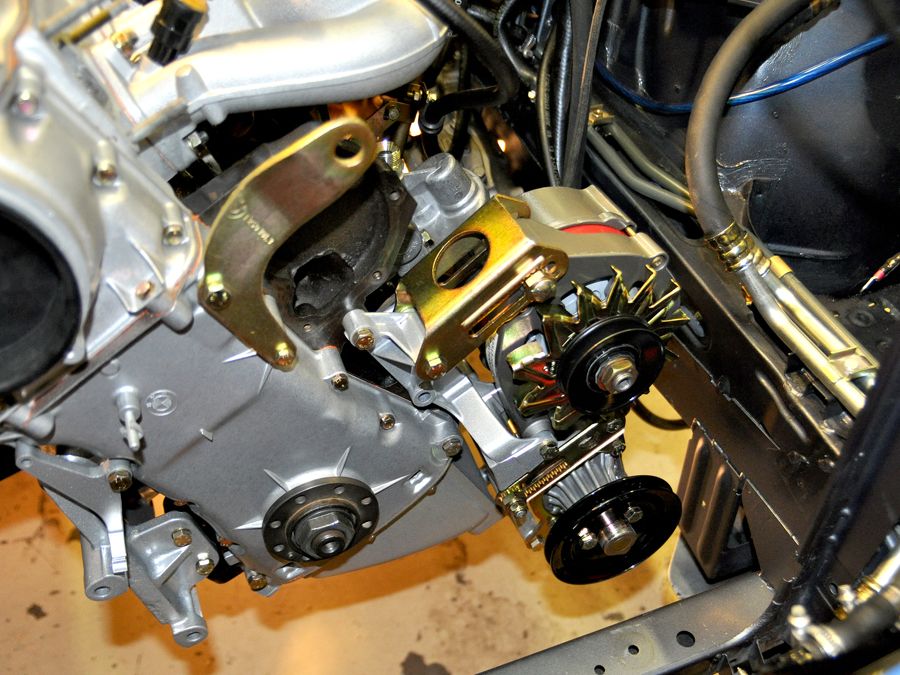
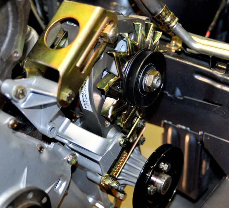
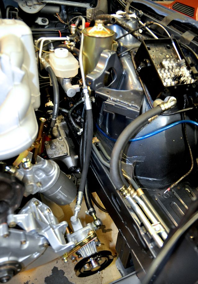
It was time to install the last of the components in hopes to get the system closed up, starting with the Power Steering Pump. The pump has been sitting on a shelf since I assembled it last month along with a box full of hoses and High Pressure Lines. First up was installing the PSP onto the bottom of the Alternator Bracket, along with all new hardware & components:
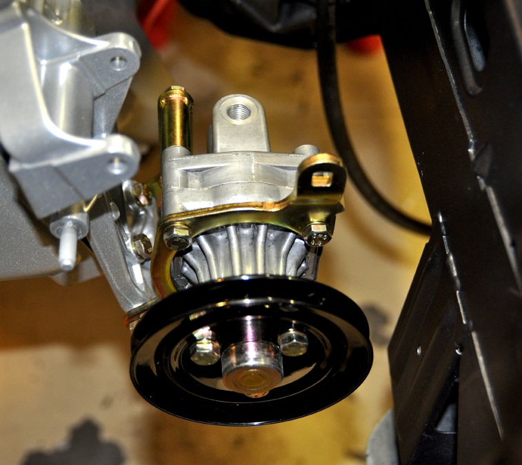
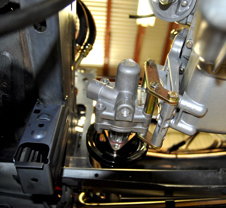
Then it was hooking up the High Pressure Hoses from the Accumulator (Bomb), Fluid Reservoir, Steering Gear Box, and the Cooling Lines. The Accumulator and one of the lines went in a while back as well as the Cooling Lines. A certain amount of the hoses went in previously also:
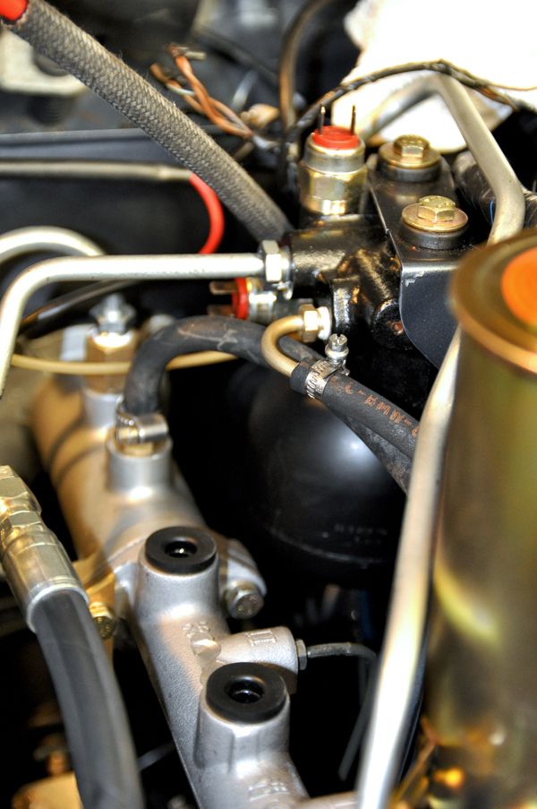
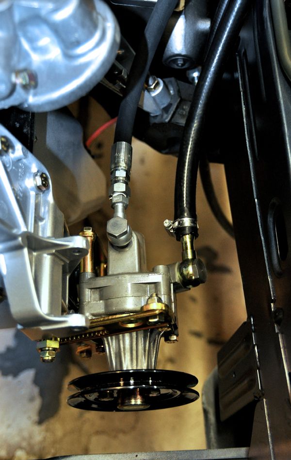
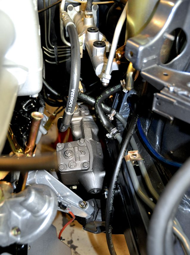
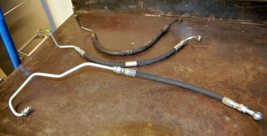
One or two of the High Pressure Lines were new from BMW but I bought three that Antony (buzzbomb) had remade with new hoses and crimped ends with some recycled fittings. I couldn’t control the process otherwise I would have had the fittings and hard pipes re-plated to match the orginals. But these look well made so I’m not complaining. Besides, they will likely be a damned sight better than the 30 year old leaking versions they replaced.
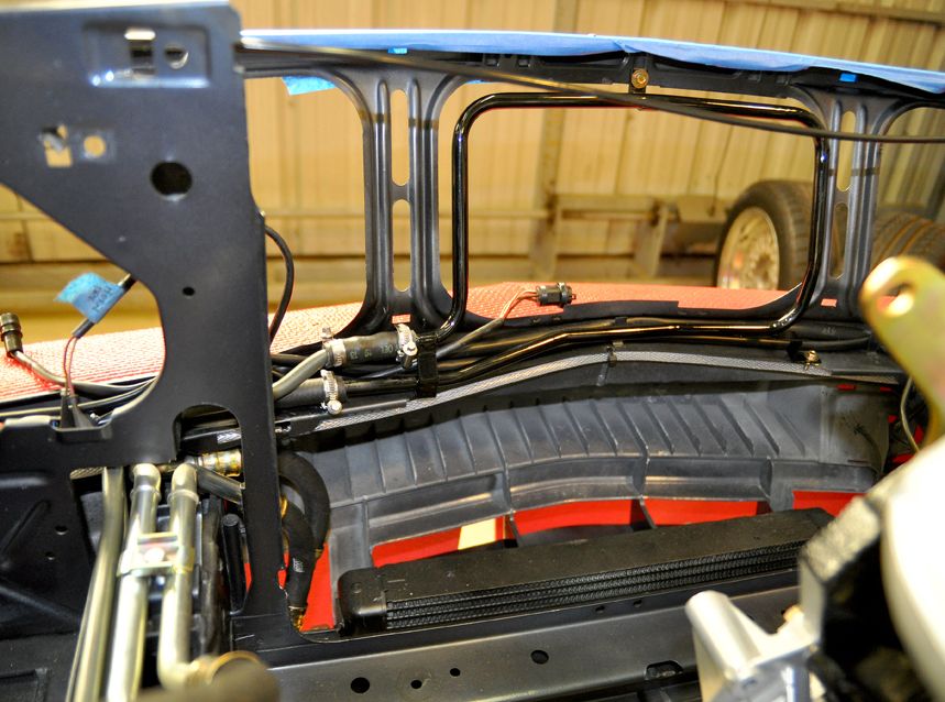
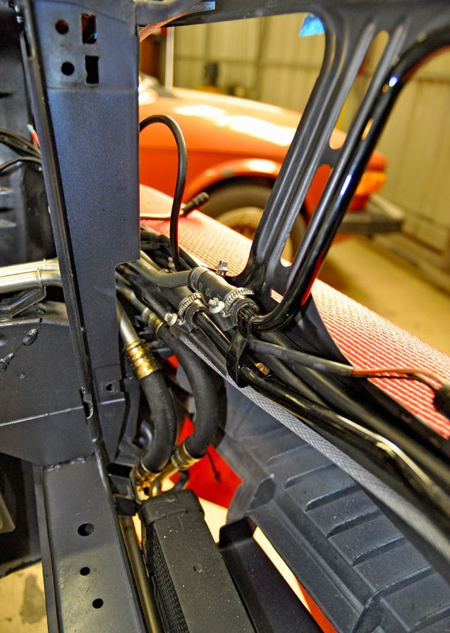
I also completed the installation of the Hydraulic Fluid Cooling loop by installing the hard pipe loop in the front nose. The hardest part of the whole procedure was connecting the loop and the two hard return and supply pipes that are bolted to the frame rail together with small sections of hoses. The two lengths of 12x18mm hose are only about 2” long but it is a bit of challenge getting them on there with the hose clamps while crammed up against the front nose frame.
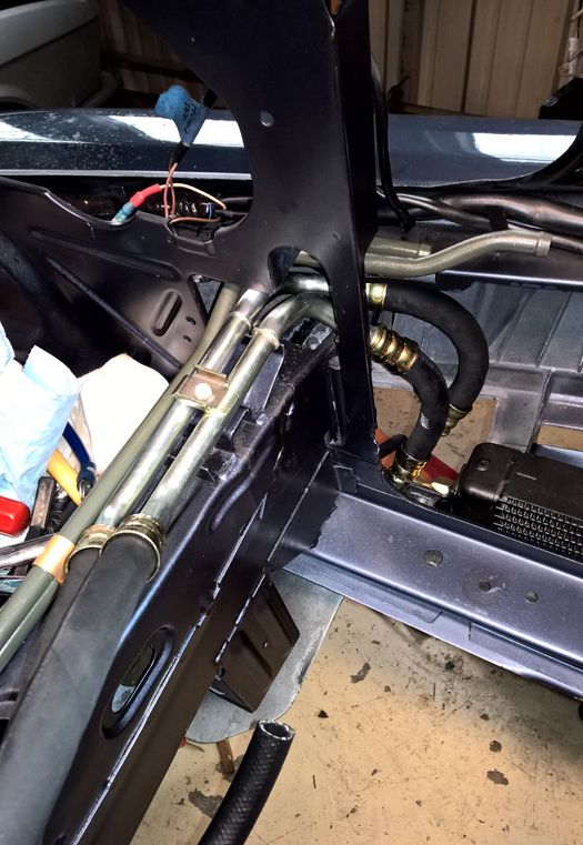

(Sorry, thought I had photos of the Cooler loop in the nose; I will take a few pics of it next weekend showing those blessed little hose sections)
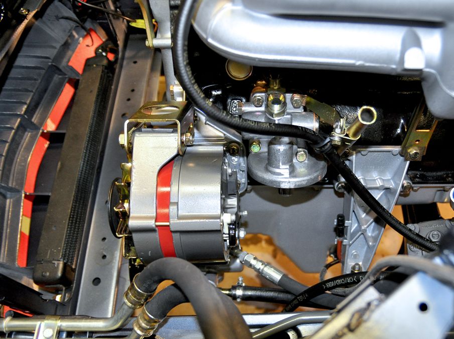
With that done I went ahead and closed up a few loose ends namely the Brake Fluid Reservoir and Oil Filter Housing. I wasn’t planning on installing the latter, but I kind of had to in order to figure out the alignment of the High Pressure Supply Line to the PSP. I will save hooking up the Oil Cooler Lines to the Oil Filter Head until after the Alternator goes in.
 ABS PUMP REBUILD:
With all that done, I returned reassembling the ABS Pump that I had left half done so I could get the Engine and Transmission installed. So I had all the parts cleaned and a few items re-plated. Turns out they could not re-plate the pump body itself; the plating process involves flowing the zinc coating through all the openings to get to all the surfaces. Since the two halves of the pump body of are sealed with small channels through them, they wouldn’t be able to do the plating process correctly. So my compromise was to clean the pump body and seal it.
Reassembly was a simple reverse process of the tear-down:
First reassemble each of the four pistons:
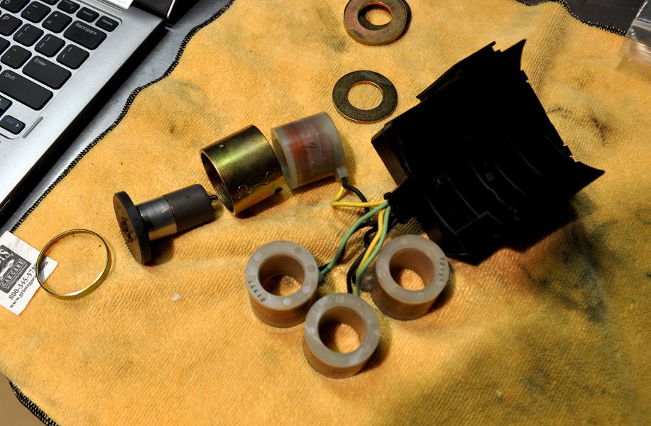
Next install the really small O-rings into the top half of the pump. It is a good idea to place in the white plastic rings at the same time. Then press the pistons down into the holes through the O-rings:
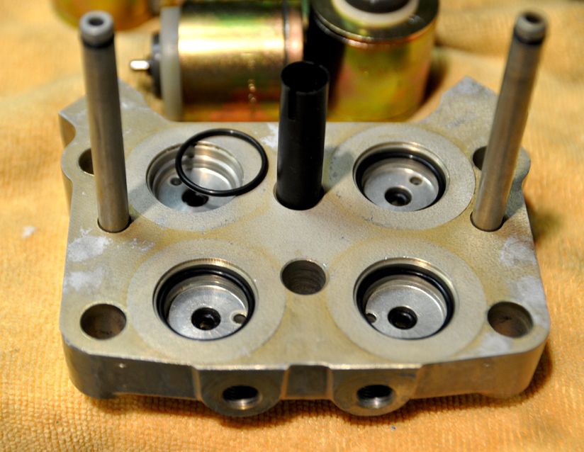
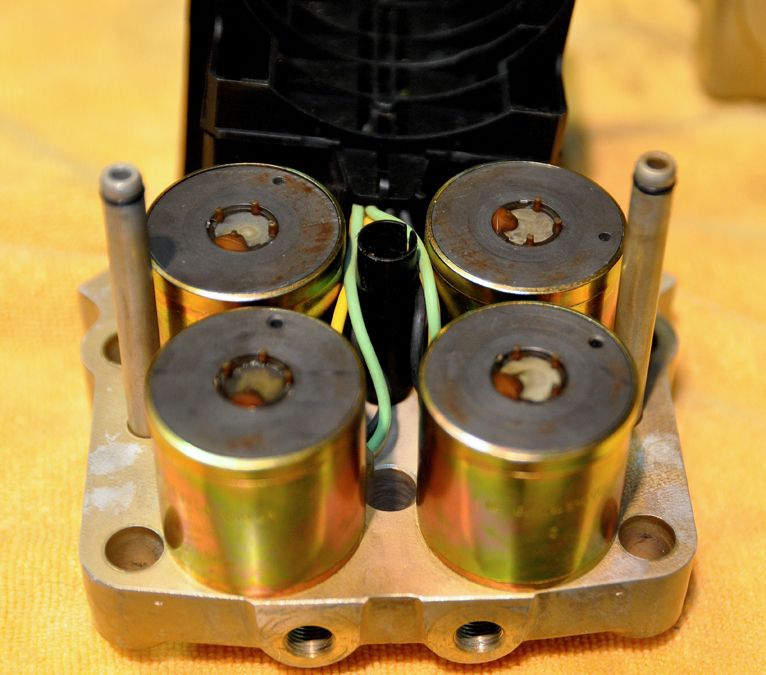
And don't forget the O-Ring gaskets on on the other half of the pump body:
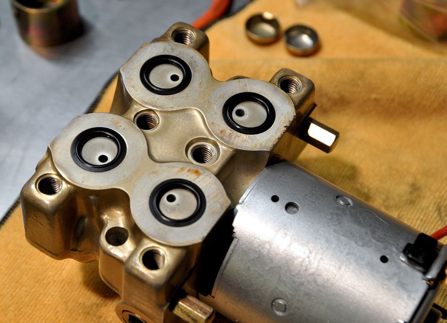
Set that aside and focus on getting the pump cylinder installed back into the pump body. Remember that small spring loaded piston and ball bearing that pumps up inside the shaft opening?
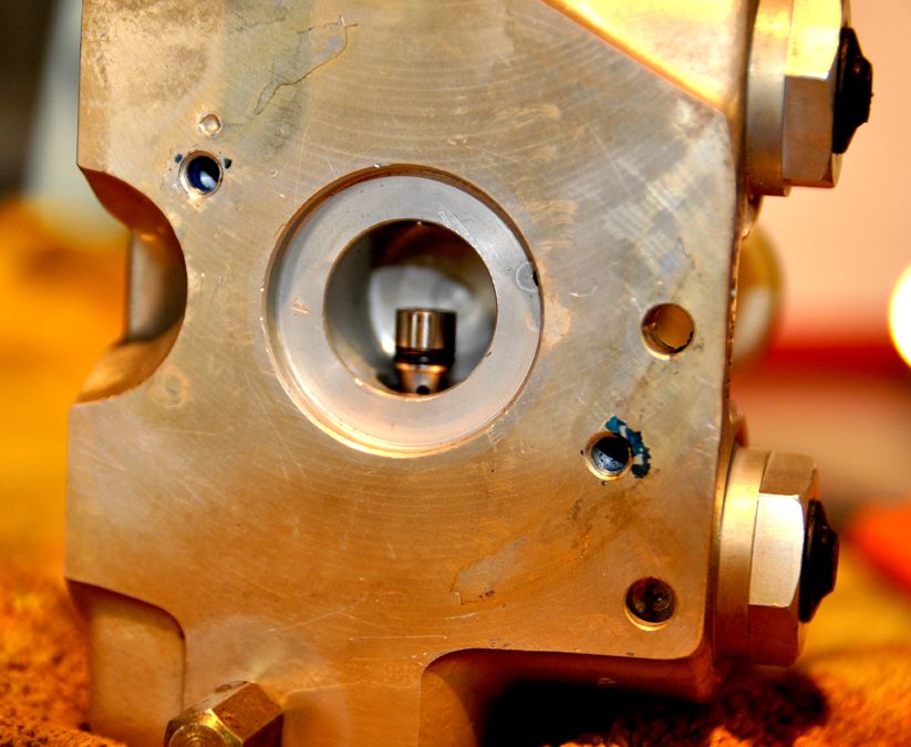
Now it was time to find a way to depress that little cylinder; turns out it is under quite a bit of pressure from the two springs. The cylinder has to be completely depressed in order to get the pump shaft into the hole. After some experimentation, I came up with modifying this piece of copper pipe by cutting the end into spiked tip and flattening and bending the tip:
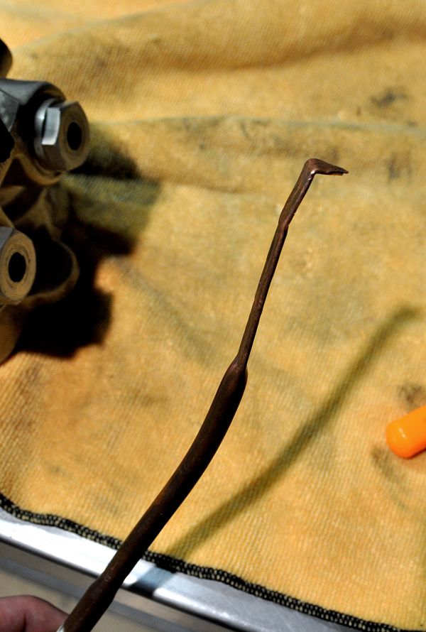
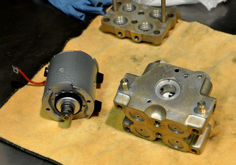
It took a bit but it worked. Kind of needed a third hand at times, but I eventually slipped the pump shaft down past the cylinder. (Okay it took several attempts where that little cylinder popped out and I had to chase the spring and ball bearing across the bench). To keep from losing your progress once you get them together, quickly install the two long case screws through the pump and into the pump body to lock them together:
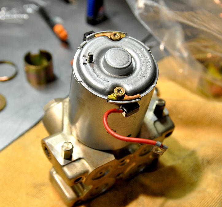
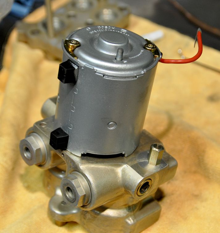
Then take the lower half of the pump body, flip it over and slip to the two pump body halves together. Careful to keep the pistons aligned and in place, press them together while making sure the wires are clear the case bolt holes. Install the six case screws with Loctite and tighten them down.
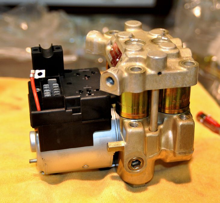
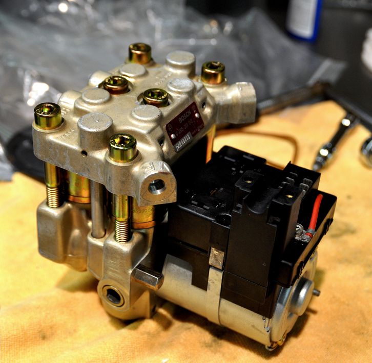
Now install the band clamp around the pump cylinder to connect the electrical Fuse Block and pump together. I had to employ C-clamp to squeeze the connector on the end of the band clamp into the Fuse Block (you could use another set of hands to do the same thing if available). Remember to feed the red power wire up through the back slot in the Fuse Block.
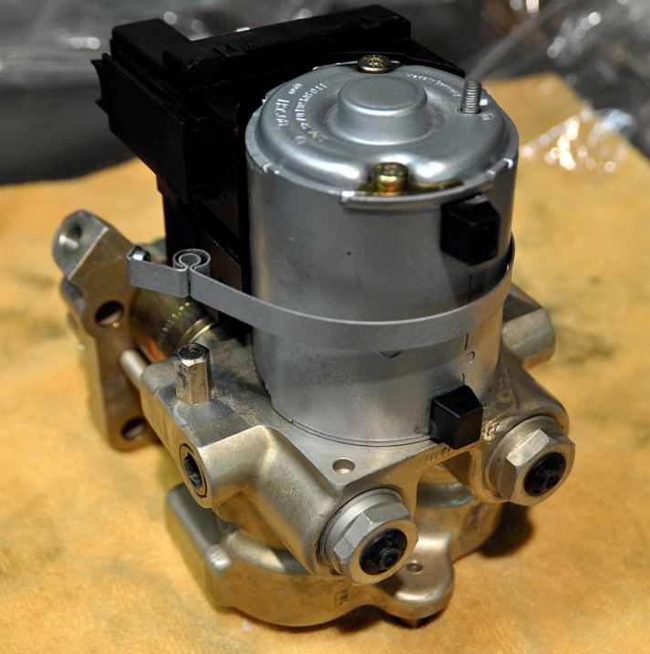
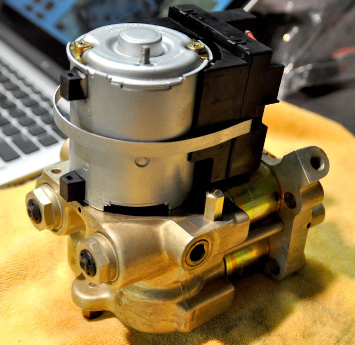
Now you are done with reassembly and ready to install it back into the Engine Bay:
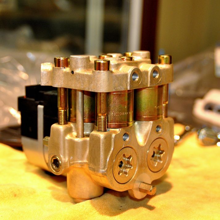
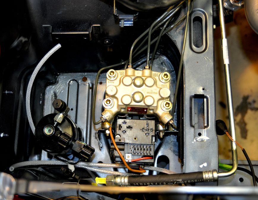
Set the ABS Pump into the front fender well, secure it down to mounting points and start reconnecting the Brake Lines back into the pump. This time I was sure not to cross-thread the lines:
 BRAKE SYSTEM:
Not a whole lot here except installing the Rear Brake Calipers (after I cleaned the rear wheel wells, of course). I finished out the Front Calipers also (Anti-Rattle Clips) as well as installing all the UUC Stainless Steel Brake Lines:
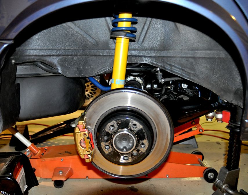
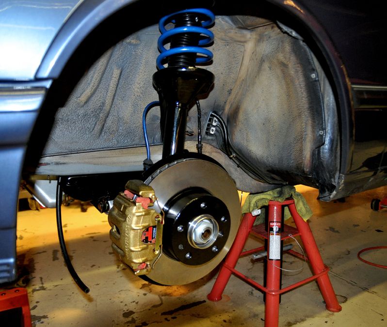
That closed up the Hydraulic and Brake System. All that is left is to fill and bleed everything.
Next week is on to Fuel and Electrical.


