Page 1 of 1
Megasquirt TPS help!
Posted: Mar 03, 2023 12:02 PM
by Dirtym30
Gurus,
Im seeking help with getting my turbo project going.
My Setup:
Megasquirt PNP2 ECU
Turbonetics 60/65 Turbo
deka 80lb fuel injectors
Stock Coil and dizzy cap
OEM Bosh crank sensor, ( I converted to Motorinc 1.3 with e34 stuff including harness)
Clutchmasters stage 3 clutch and stock flywheel.
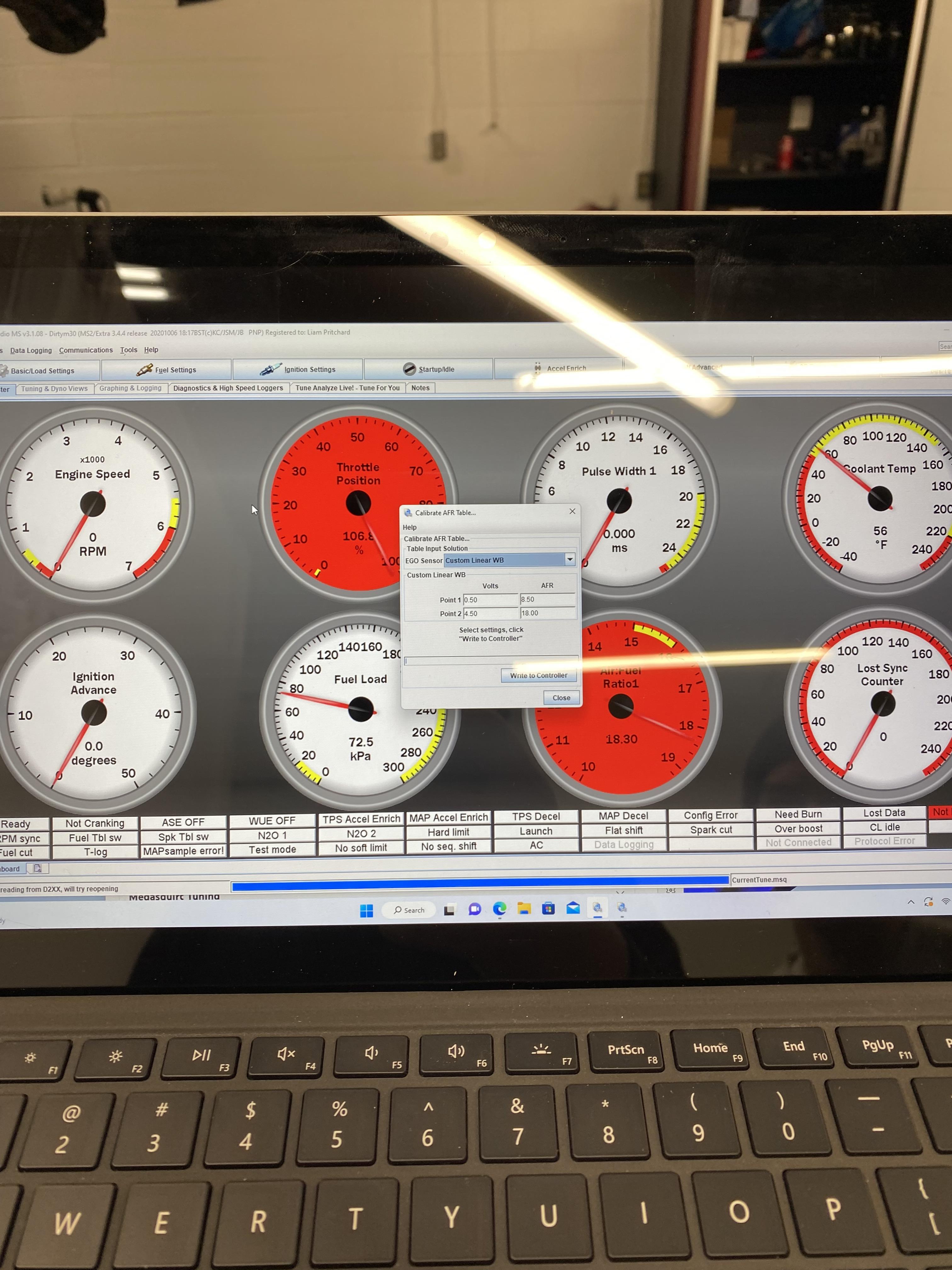
I have a base tune loaded and some parameters set and am ready for a first start/drive but my throttle is reading full when there is no input. no response when attempting to calibrate it.
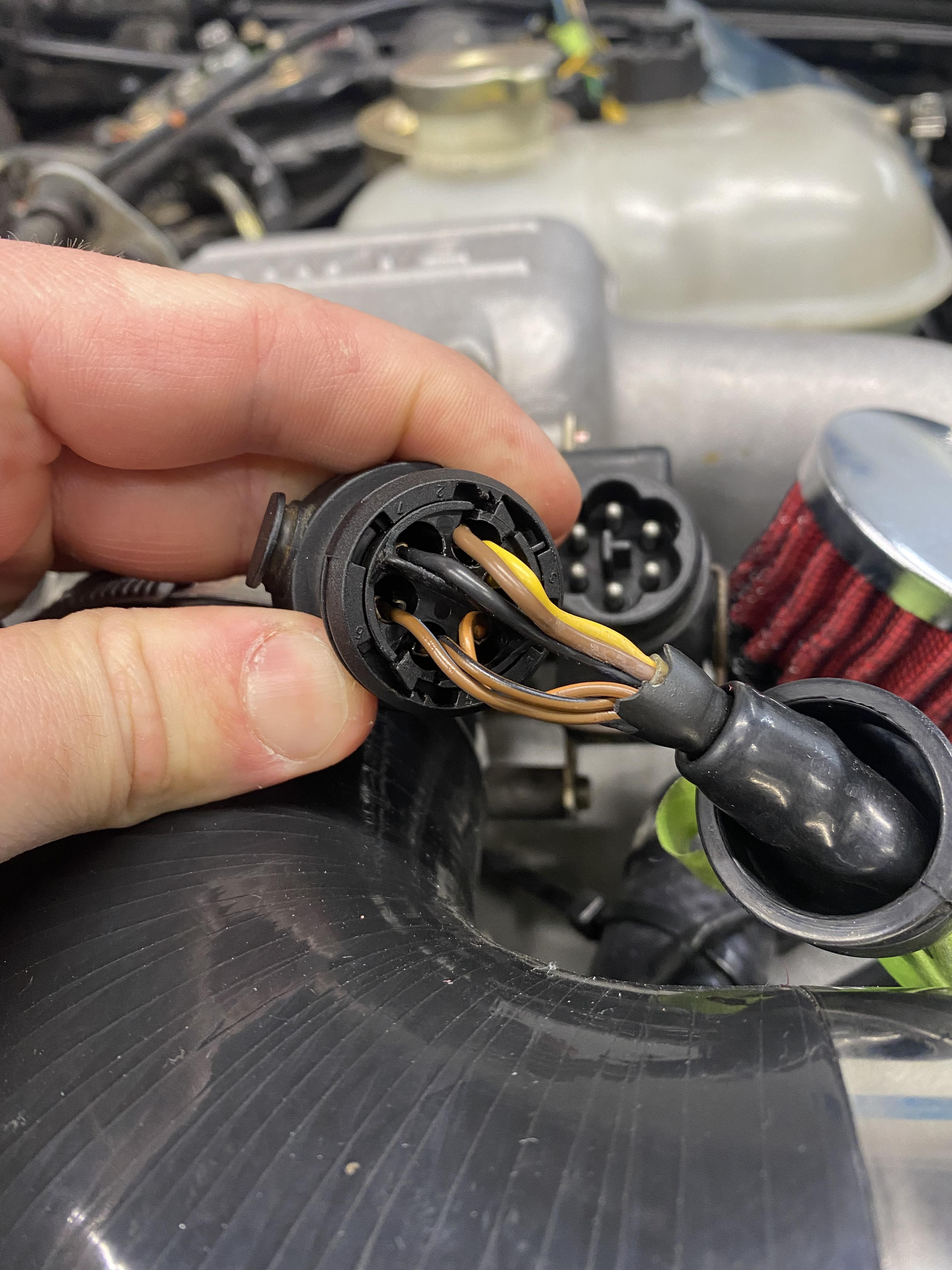
I have the 1.3 style 6 pin TPS unit installed. Any insight would be much appreciated.

I hope all your winter projects are going swell.
Re: Megasquirt TPS help!
Posted: Mar 03, 2023 8:18 PM
by turbodan
First question I have is about the menu you have pulled up in that image. That would be the O2 sensor table calibration menu, the TPS calibration is done on a different menu. Under tools, should have one that says calibrate TPS. You tell it to read the current value with the throttle closed, then again at full throttle. Have you done this?
If it's still out of whack after doing that, you have either a wiring issue or a bad TPS. Wiring issue is likely.
Re: Megasquirt TPS help!
Posted: Mar 04, 2023 1:13 PM
by Dirtym30
I know thats for the O2 Its the only pic I had to show the tps signal.
Its to do with the wiring, From what I can read online the top 3 pins (123) are for the potentiometer input and the bottom (456) are switch wires.
The bottom three have continuity to the ecu, Specifically 4 has a signal at pin 53 which should be 5 volt ref.
pin 5 should be ground and Pin 6 I can trace to pin 55 AND 52 on the ecu which should read signal.
Im Lost here clearly.....

Re: Megasquirt TPS help!
Posted: Mar 04, 2023 2:58 PM
by iamcreepingdeath
Check out my last post in the megasquirt FAQ:
viewtopic.php?p=1522001#p1522001
Re: Megasquirt TPS help!
Posted: Mar 06, 2023 11:09 AM
by Dirtym30
SOLVED
Thanks for the input guys.
I ended up tracing the brown/blue to pin 53 on my 1.3 harness. Brown black went to pin 52, 3rd wire = ground.
The top three wires for the switch (Blue, Brown, yellow) I traced to an unused connector inside the car. It is likely it was used for some type of throttle module on the e34 doner car. the problem is the top three wires are for the potentiometer side of the switch, which is what I need the MS to see. Not the bottom three which are for WOT and idol inputs.
So essentially I just flipped them so the ECU would see the potentiometer side of the switch.
What I did,
Brown/Blue - Blue = Signal
Brown/Black- Yellow = 5 volt
Brown/cream? - brown = ground.
Tuner studio now reads like a dream.


